When transferring Tekla Structures connections to RISAConnection properties are mapped over from Tekla Structures to RISAConnection and vice-versa. Tekla Structures and RISAConnection are very different and were built for different applications. Because of this there are items that don't map exactly as you might expect. Here we will elaborate on some of these items.
For vertical brace connections, the RISA-Tekla Link allows the transfer of Components 141 or 146 (beam-to-column) in combination with Components Wraparound Gusset (58), Hollow brace wraparound gusset (59) or Wraparound gusset cross (60) (brace to beam-column intersection). This connection will come over as the Vertical Brace Diagonal Connection in RISAConnection.
For this transfer to work, some basic requirements must be met:
Beyond these requirements there are more specific items that must be set properly on the component to perform the transfer:
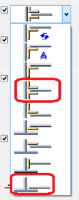
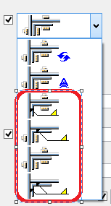

There is a potential for one, two, three or four braces to come into a single column/beam joint. In RISAConnection only a single "side" of the column is considered for an individual connection. if four braces come in this will be split into two separate connections for the two sides of the connection.
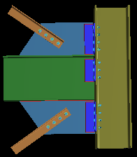
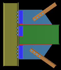
From here the RISA-Tekla Link determines the eccentricity of the braces. RISAConnection has three categories: Concentric, Along Beam, Along Column. Thus, the link will calculate the workpoint locations for the braces/beam/column to see how they line up and then group them accordingly.
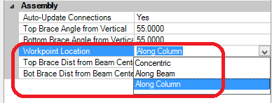
For the Along Beam case RISAConnection requires the eccentricity to be equal for the top and bottom braces. In Tekla Structures there is no requirement for this. Thus, if both the top and bottom brace workpoints land along the beam they must also land at the same location. In the RISA-Tekla Link we give a +-2" on this workpoint location. If the brace workpoints land within 2" of one another the program will take the larger value and bring that into RISAConnection. If the brace workpoints are greater than 2" from one another then the connection will not be supported.
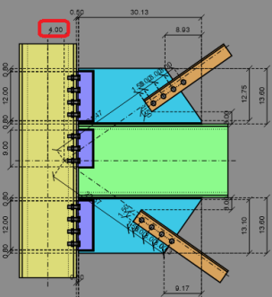
For the Along Column case RISAConnection allows different eccentricities for both top and bottom braces that are eccentric along the column. If the RISA-Tekla Link finds a scenario where both top and bottom brace workpoints land on the column then they will come over exactly as is.
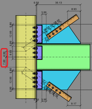
For the Concentric case if the beam/column, top and bottom workpoints all hit concentrically it will come over as concentric. If both the top and/or bottom braces are eccentric from the beam/column workpoint by <= 2" then the program will bring this connection in as concentric.
If braces are eccentric >2" and workpoints for both top and bottom braces don't land on the same element (beam or column) then this connection will be unsupported.
Tekla Structures does not have a single shape element for double angles. To create a double angle configuration in Tekla Structures you must either explicitly draw two angles.
For double angle braces to be supported in RISAConnection they must:
Note:
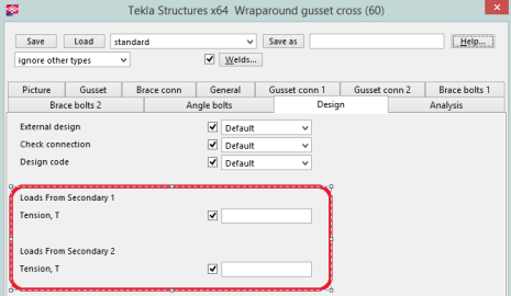
Regarding loading of double angle braces the program will sum the loads from Loads from Secondary 1 and Loads from Secondary 2 and bring that total to RISAConnection.
In RISAConnection, the distances on either side of the gusset clip angles are always the same. Thus, if unequal distances are given in Tekla Structures the program will take the average of these values and use them for both sides of the gusset.
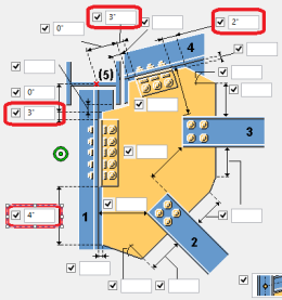
|
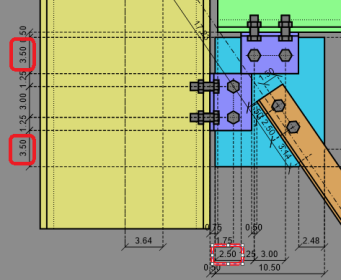
|
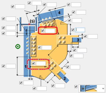
Tekla Structures and RISAConnection do not have a matching dimension for the gusset clip. However, these dimensions are used to transfer the clip.
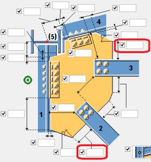
These two dimensions are added together with the width and angle of the brace and used to determine the Gusset Clip in RISAConnection.
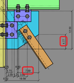
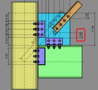
RISAConnection and Tekla Structures have similar inputs for this value.
|
|
However, we can see in Tekla Structures that the dimension goes directly to the face of column and in RISAConnection this is dimensioned to the connector. This is accounted for in the RISA-Tekla Link.
For chevron brace connections, the RISA-Tekla Link allows the transfer of Components Bolted Gusset (11) and Tube Gusset (20). This connection will come over as the Vertical Brace Chevron in RISAConnection.
For this transfer to work, some basic requirements must be met:
Beyond these requirements there are more specific items that must be set properly on the component to perform the transfer:


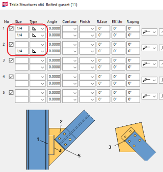
Note:
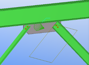
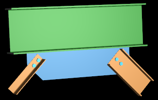
Chevron braces are integrated whether they frame into a beam or a column. For beam framing it is relatively easy to understand the front of the brace and how mapping should occur.
|
|
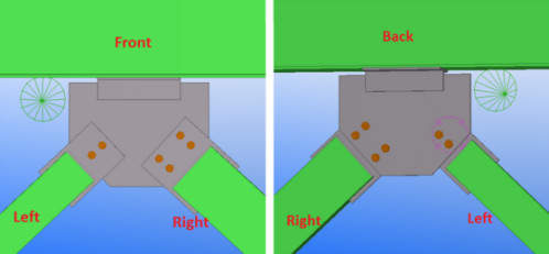
However, for columns the orientation is more complex. Here's how it works:
If the connection is built from one column and two braces then the connection will always come over in the below the beam configuration, rather than above.
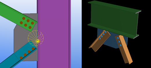
The left and right brace is determined by using the coordinate system of the connection (in the direction of the cone)

If one or more of brace has an asymmetrical shape relative to the gusset (Angle, T-shape, C-shape) then the orientation of this brace determines the front side of the connection. In this case left and right brace are determined by the front side of connection.
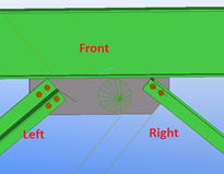
If both braces have an asymmetrical shape relative to the gusset (Angle, T-shape, C-shape) AND braces are oriented in different directions then the front side of connection can not be determined. In this case the connection will not be transferred to RISAConnection.
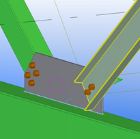
For single column base plate connections, the RISA-Tekla Link allows the transfer of Component US Column Base Plate (1047). This connection will come over as the single column base plate connection in RISAConnection.
For this transfer to work, some basic requirements must be met:
Beyond these requirements there are more specific items that must be set properly on the component to perform the transfer:
The base plate profile must be rectangular. The base plate dimensions and material are mapped with the following options below:
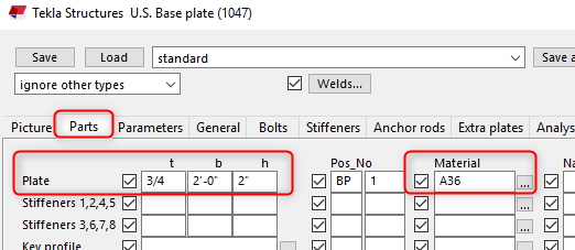
Note:
The material strength for the concrete support may be defined under the Anchor Rod tab under the option boxed below.
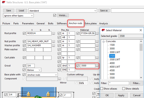
The concrete support dimensions are not available in Tekla Structures, so the user will have control over these inputs in RISAConnection. During the initial transfer the concrete lengths and widths will assume 1.5*Column Depth/ Width respectively.
The anchor bolt diameter and material may be selected from the following options below:
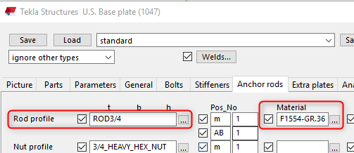
RISAConnection supports the following bolt layouts:
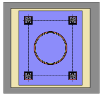
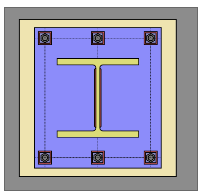
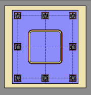
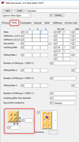
The edge distance in RISAConnection is mapped to Tekla's bolt edge distance to shim plate. When this input is blank, a default value of 30mm or 1.18in is used.
Note:
The base plate column flange and web weld size and type map to Tekla Structures weld options 1 and 2 respectively:
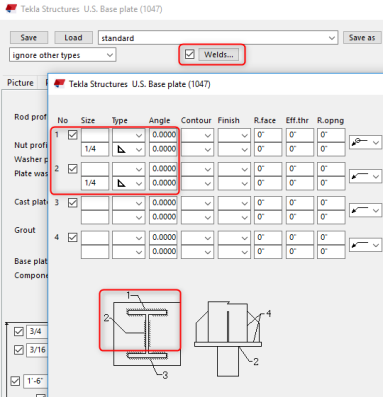
Note:
Plate washers can be added between the anchor bolts and column base plate. The plate washer size and material options are defined below:
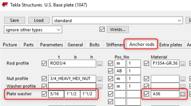
The plate washer weld in RISAConnection is defined between the washer and the base plate. However Tekla Structures does not have an option for this. Instead, the weld between the plate washer and anchor attribute is used by the link. To set the plate washer weld:
1. Select objects in components and then select the plate washer weld to define the properties of the weld:
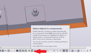
Note:
RISAConnection’s plate washer must be square, so use the smallest width or height dimension input in Tekla Structures if they are not equal.
Tekla Structure's Base Plate connection component 1047 does not contain loading considerations. RISAConnection will use the Column End Forces to map the loads.
Note: